|
|
|
|
| Microwave tubes: L-band pulsed TWTs |
 |
The traveling wave tube ( TWT) is used as a driver or output tube in advanced radar systems and test equipment.
Each tube delivers a peak output power in frequency range without adjustment.
A ceramic-metal construction provides exceptional mechanical strength.
Electron beam is focused by periodic permanent magnet (PPM) structure.
Due to the type they are cooled by forced liquid or air circulation.
Some types requires mixed, air-liquid cooling or conducts heat to the base.
Wroclaw Division of PIT-RADWAR S.A. manufactures the following types of TWTs:
|
L-band pulsed TWTs
|
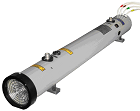 |
L-band pulsed TWT can be used a driver or output tube in advanced radar system and test equipment.
Depending on the type, they use helix, ring and loop or ring and bar slow wave circuit.
The tubes have a metal-ceramic vacuum envelope and periodic permanent magnet focusing structure.
The heat is discharged by conduction to the base or TWTs are cooled by forced liquid and/or air circulation.
Basic parameters of L-band pulsed TWTs see below.
Additional information are attainable in section Documentation » Data sheets.
|
|
| Technical parameter specification of L-band pulsed TWTs |
|
| |
Type of TWT |
Frequency range [GHz] |
Peak output power [kW] |
Gain [dB] |
Duty cycle [%] |
Cooling |
| |
LO-111 |
1,24÷1,44 |
5 |
26 |
1 |
liquid and air |
| LO-112 |
1,24÷1,44 |
10 |
30 |
1,3 |
liquid and air |
| LO-120 D |
1,24÷1,34 |
40 |
35 |
2 |
liquid |
| LO-120 C |
1,34÷1,44 |
| L13CC |
1,2÷1,5 |
20 |
32 |
2 |
conduction |
| L113A |
1,0÷1,5 |
10 |
27 |
1 |
air |
| L113A2 |
1,0÷1,5 |
10 |
27 |
2 |
air |
| L113B |
1,0÷1,5 |
3,5 |
20 |
2 |
air |
| L113C |
1,0÷1,5 |
4,0* |
21 |
4 |
air |
| L114 |
1,5÷2,0 |
7 |
27,5 |
1 |
air |
| L114U |
1,5÷2,0 |
8 |
28 |
1 |
air |
| L114U2 |
1,5÷2,0 |
8 |
27.5 |
2 |
air |
| L13 |
1,2÷1,5 |
20 |
32 |
2 |
liquid |
| L13M1 |
1,48÷1,58 |
40 |
32 |
2 |
liquid |
| * |
Presented power is available for bandwidth 200 MHz from given frequency range.
|
|
|
|
|
|
|
back to top
|
|
